SuperCam
mission specific
Instrument Overview
SuperCam is an integrated multi-sensor remote-sensing instrument carried aboard the Mars 2020 rover. It implements four spectroscopic techniques to remotely measure properties of materials on Mars. These include:
- Laser-induced breakdown spectroscopy (LIBS)
- Raman spectroscopy (Raman)
- Time-resolved fluorescence spectroscopy (TRLS)
- Passive spectroscopy - Visible and Infrared spectrometer (VISIR or VIS)
SuperCam also includes a telescopic color context camera, the Remote Micro-Imager (RMI), which is principally used to document the sites of remote spectroscopy measurements. Finally, the instrument also includes a microphone, which is used primarily to measure the pressure wave produced by the generation of plasma at a LIBS target. As a science instrument, it produces a single science data product at each observing point (target or raster point) per observation mode (LIBS, Raman, TRLS, VISIR, microphone). SuperCam builds on the experience of ChemCam on MSL. This former instrument had very much the same overall architecture and operation scheme but only included LIBS and RMI.
SuperCam's spectrometers can be pointed at targets in the rover’s environment, thanks to key components being mounted on the rover’s Remote Sensing Mast. The SuperCam Mast Unit (SCMU) is the remote sensing head that interrogates the Martian surface by firing laser pulses and collecting light back through a small telescope on the rover mast. The light collected is directed into an optical fiber and sent to the body unit for spectral analysis. The SCMU also contains an infrared spectrometer (IRS) for passive spectroscopic analysis at long wavelengths, without the use of its lasers. The microphone and Remote Micro-Imager (RMI) are also located in the SCMU, which is housed on the M2020 rover sensing mast (RSM). The SuperCam Body Unit (SCBU) is housed inside the rover body, in direct contact with the thermal RAMP (Rover Avionics Mounting Panel). This unit performs most of the light spectral analysis in its 3 spectrometers: UV, violet (VIO), and visible to near-infrared (VNIR). In passive mode (no laser) the spectra of interest come from the IRS, the VIO and the VNIR, a combination referred to as VisIR. The SCBU interfaces with the rover for electrical power and communication. It also interfaces with, and provides power to, the Mast Unit. Mounted close to the Multi-Mission Radioisotope Thermoelectric Generator (MMRTG) on the rover, the SuperCam Calibration Target (SCCT) is about 1.56 m away from the RSM. It contains representative samples of minerals and crystals and will be used to refine/cross-calibrate/validate the calibration of the instrument established before launch, on Mars. It also carries a Titanium target for LIBS calibration, black and white targets for IR spectroscopy calibration and geometrical patterns (USAF1951 target and others) for optical performance assessment and calibration of the RMI camera.
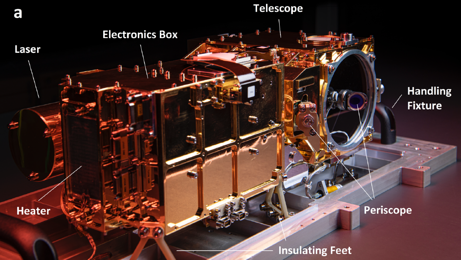
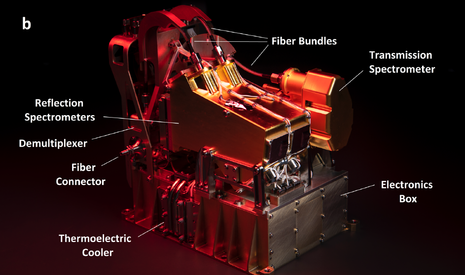
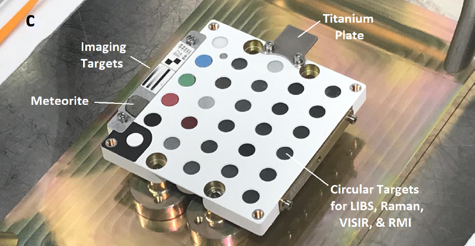
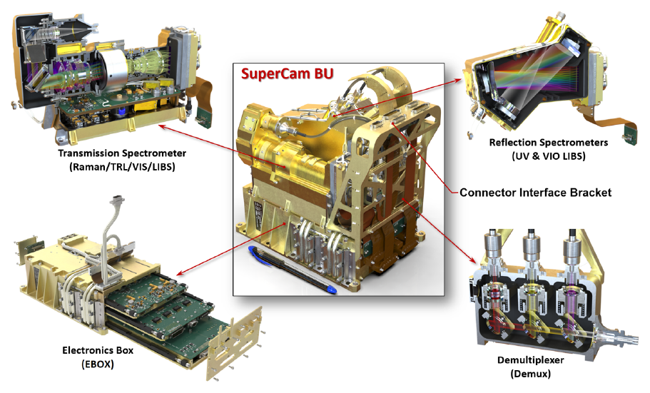
The SuperCam instrument is shown in the figure below, consisting of the Mast Unit (MU, top), the Body Unit (BU, middle), and the SuperCam Calibration Target (SCCT, bottom). As part of the MU (top), the laser can be seen to the left, protruding from behind the electronics box. The telescope is at the far end, at the center of which the periscope mirror for the green laser beam is mounted. The corresponding periscope mirror can be seen just past the electronics box, facing away from the camera. At the near end of the electronics box, a heating pad is just to the left of the connectors. The Mast Unit is mounted on insulating feet, and is shown here resting on a handling fixture. The BU (middle) shows a transmission spectrometer resting behind two identical reflection spectrometers, all mounted on top of the electronics box. Three optical fiber bundles can be seen with their protective shields near the upper left; these transfer light to the spectrometers from the demultiplexer. The only part of the demultiplexer that is visible is the AVIM fiber connector, protruding at the left center. This is where the light from the Mast Unit enters the Body Unit. One of three sets of thermo-electric coolers are seen in the lower center, identified by two visible heat pipes that run under the spectrometers to cool their detectors. On the SCCT (bottom), twenty-nine circular targets and several other calibration targets are mounted. The protruding titanium plate at the upper right is used for wavelength calibration via LIBS spectra. Optical targets line the left side.
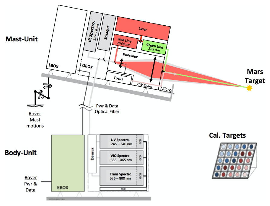
The Mast Unit (MU) consists of the main laser which provides two wavelengths, the telescope, a continuous-wave (CW) laser for focusing, and a microphone. The optical box (OBOX) is completed by the infrared (IR) spectrometer and the Remote Micro-Imager (RMI). An electronics box (EBOX) controls and powers the various subsystems in the MU. Acquisition of the target is provided by the rover mast motions. Electrical cable and an optical fiber connect the Body Unit (BU) to the MU. The fiber carries light in the 245-853 nm range to the demultiplexer (demux) in the BU, which distributes the light into three spectrometers covering ultraviolet (UV), violet (VIO), and visible to near infrared spectral ranges. The latter is characterized by a transmission spectrometer. The electronics box (EBOX) in the BU operates the instrument, provides power to the BU spectrometers and the MU, and communicates with the rover. A set of calibration targets (Cal Targets) are mounted on the back of the rover to facilitate calibration while on Mars.
The SuperCam Body Unit is shown in the figure below. The base of the Body Unit contains DPU (Digital Power Unit) electronics and power supplies and is thermally sunk to the RAMP (Rover Avionics Mounting Plate). On top of, and thermally isolated from, the base (and the RAMP) are the instrument’s Raman and UVIS Spectrometers.
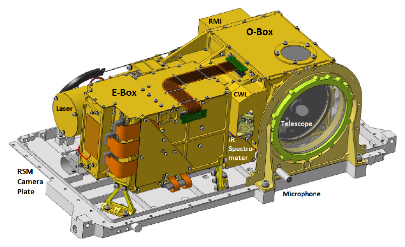
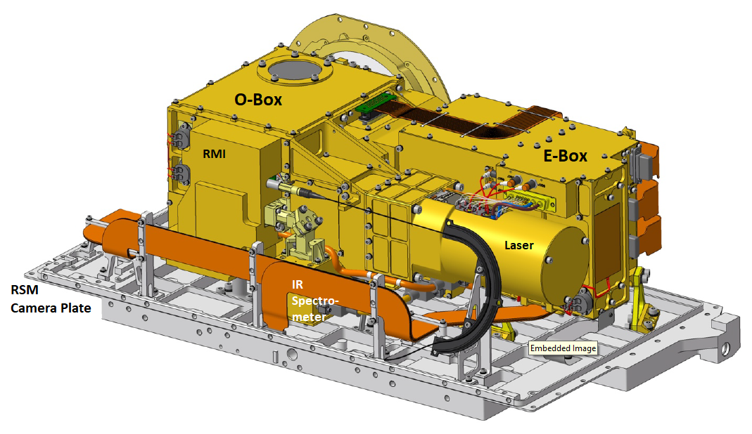
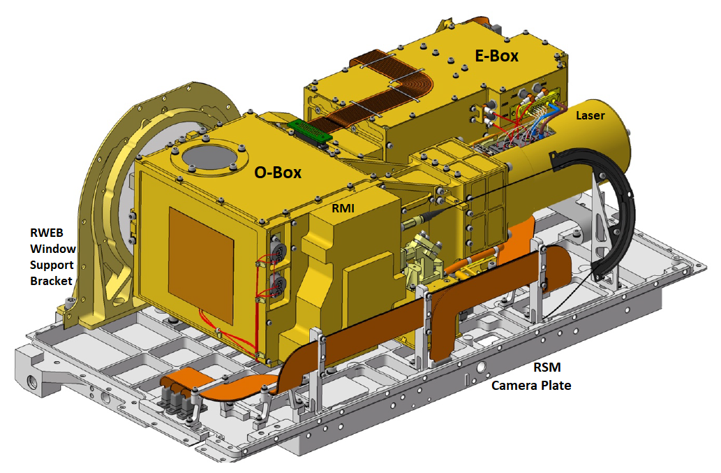
The SuperCam Mast Unit is shown in the figure below, shown from three different angles. The Optical Box (O-Box) contains SuperCam's telescope (green ring and adjacent box, top image), Remote Micro Imager (RMI) (back of telescope optics box), and the Continuous Wave Laser (CWL) used for focusing. The tubular horizontal housing towards the rear of the Mast Unit contains the LIBs/Raman laser and is rigidly attached to the O-Box. Attached underneath the O-Box is the IR spectrometer. The Electronics Box (E-Box) (adjacent to the laser) contains the Mast Unit’s controller electronics. The O-Box and E-Box are mounted to the RSM (Remote Sensing Mast) camera plate on flexures. The microphone is mounted on the RWEB (Remote Warm Electronics Box) window support bracket. The details for the mechanical accommodation are contained in the SCMU Source Control Drawing (SCD).
SuperCam Remote Micro-Imager (RMI)
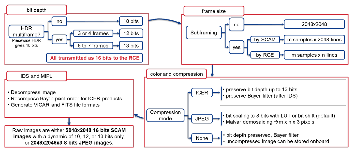
The SuperCam RMI camera subsystem is packaged onboard the rover in two instrumentation units: the Mast Unit affixed to the RSM (see figures above), and the Body Unit housed within the rover WEB. The RMI camera provides high-resolution color context images of the LIBS sampling area as well as imaging rock morphologies and distant features. It includes an adjustable focus capability with 2048 x 2048 CMOS color detector (Bayer Filter). Raw RMI images are 10- to13-bit (coded on 16-bits) and are often transformed onboard into four images of 1024 x 1024 pixels each consisting of the red, green1, green2, and blue (RGGB) Bayer cells in separate images.
RMI optics characteristics useful in the analysis of EDR and RDR products are described in the first table below. RMI image data return compression modes are listed in the second table below. The camera acquisition of the scene and subsequent onboard storage and readout of image data is illustrated in the figure below.
| SuperCam RMI Operational Characteristics | |
|---|---|
| Characteristic | Value |
| Resolution (S x L) | 2048 x 2048 |
| Bit Depth | 12 |
| Field of View (FOV) useful |
18.8 mrad |
| Field of View (FOV) full frame, including dark corners | 20.6 mrad |
| Spatial Resolution with 20% contrast | 80 μrad/pixel |
| Angular Resolution | 10 μrad/pixel |
| Spectral Bandpass (99%) | ~380 - ~660 nm |
| Focus Range | ~1.05 m to infinity |
| Number of Spectral Filters |
Depth of Field ~2.5 mm at 1.56m ~9.5mm at 3m ~10.5 cm at 10m |
| RMI compression modes | |
|---|---|
| Mode | Description |
| 0 | No compression |
| 1 | ICER |
| 2 | JPEG |
RMI image data formats
Investigation Techniques
SuperCam will use a suite of spectroscopic, optical and acoustic techniques to investigate the Martian environment. An overview of these techniques is provided here and after that they will be grouped into instrument "operation modes". The surface of Mars is covered by dust. Using the LIBS laser we can remove or ablate the dust. The LIBS, Raman, and VISIR analyses can be done in any order, but the Raman and VISIR normally benefit from the partial dust removal provided by LIBS, so usually they will be done after the LIBS. There is also the possibility to do a small number (5) shots to remove dust without doing the full standard 30 shot series. The first figure below illustrates the general operational flow of SuperCam, while the second figure below discusses the relative footprints and ranges of the cameras and spectrometers.
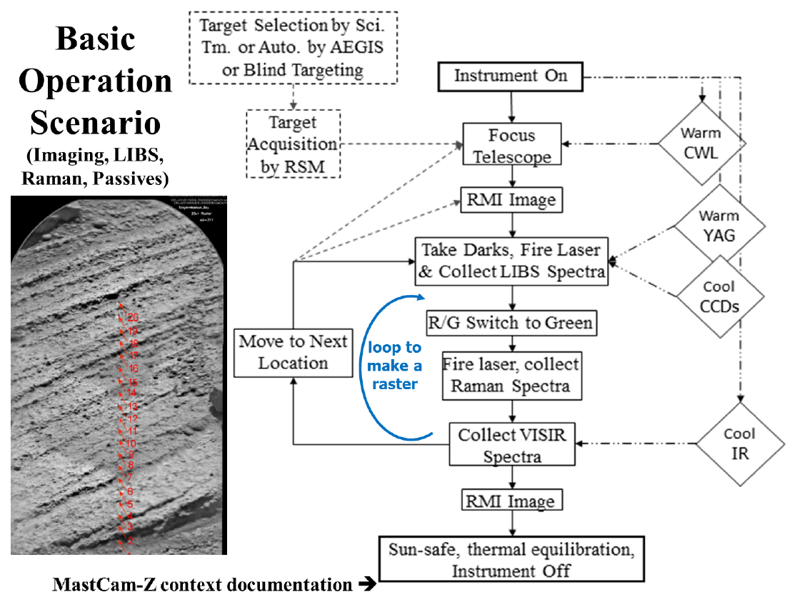
SuperCam Operations Scenario. “R/G” is “red/green” where “red” = LIBS infrared laser beam; “green” = green Raman laser beam. SuperCam switches laser beams when going from LIBS to Raman spectroscopy.
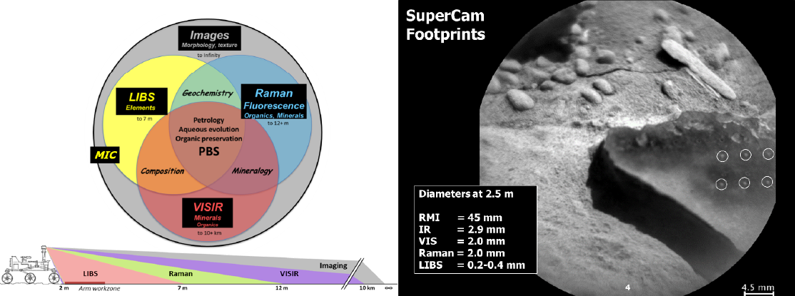
SuperCam component synergy, all working within the arm work zone and with typical measurement footprints. “MIC = microphone”. The left upper Venn diagram shows the overlap between science topics explored by the SuperCam spectrometers, camera, and microphone. The left lower diagram shows the target distances from the rover which can be observed by LIBS, Raman, and VISIR spectroscopy. Distances are all inclusive (i.e. from 2 m to 12 m, in the case of Raman). The right diagram shows the relative footprint (“beam”) size for RMI and the spectrometers for a target at 2.5 m. RMI range is 1 m to infinity.
LIBS Active Spectral Data Collection
This technique uses the mast unit LIBS laser beam to generate plasma clouds from target rocks, analyzing the resultant emissions with the body unit spectrometers to provide insight into the chemical makeup of the target rock. The LIBS laser is infrared (“red” laser). Single point observations as well as rasters made up of a collection of points will be achievable in this observation mode. The standard LIBS analysis will be 30 laser enabled shots. The wavelength range is ~240-855nm.
We will also use the spectrometers to collect background light from the environment without the laser, using the same exposure duration. These "LIBS darks" are subtracted from the active LIBS spectra as part of the data processing. Darks will be taken just before, just after, or before and after the active collection. Typically, 30 darks will be averaged for better statistics; this can be done onboard to save data volume. Dark (i.e. no laser) spectra are subtracted from the laser-active spectra to remove instrument noise or background.
Raman Active Spectral Data Collection
SuperCam Raman spectroscopy uses 532 nm green Raman laser beam to induce inelastic Raman scattering in a material where shifts in the scattered light are related to material properties, such as molecular bonds that can be used to determine mineralogical composition. The Raman signal is analyzed with the body unit transmission spectrometer. A short 100 ns exposure duration is used to minimize interference from luminescence. Single point observations as well as rasters will be achievable in this observation mode. The spectral exposure delay will need to be advanced for distant targets to allow the light time to return to the instrument. (Round-trip light time for each 10 m increment is ~60 ns). The minimal number of shots is 100, which may be collected as 10 co-additions 10 times.
Raman darks will also be taken either just before or just after the active exposures. Dark (i.e. no laser) spectra are subtracted from the laser-active spectra to remove instrument noise or background.
Time-Resolved Luminescence Data Collection
This is a sensitive discriminator of short-lived organic matter (typically < 200 ns) from longer-lived inorganic luminescence centers (typically <1 ms). The SuperCam time-resolved luminescence experiment is designed to operate by collecting spectra at variable delay times, where delay refers to the time between firing the green laser and triggering the intensifier. Identification of organic material is accomplished by scanning the minimum 50ns intensifier integration window from 0 to 200 ns delay. In contrast, long-lived inorganic luminescence is detected with a long intensifier window, generally from between 1 us to 0.5 ms, the expected max delay is <20 ms and width of <0.5 ms from the laser trigger. It is also possible to collect a single luminescence spectrum, either at a time delay that collects the Raman signal as well as luminescence or shortly after the Raman signal has completed to avoid confusion between the two signals. Single point observations as well as rasters will be achievable in this observation mode. No-laser "dark" spectra will also be taken either just before or just after the active exposures. Dark (i.e. no laser) spectra are subtracted from the laser-active spectra to remove instrument noise or background.
VISIR Spectral Data Collection
Using the infrared spectrometer on the Mast Unit, the VIO reflection spectrometer and the transmission spectrometer on the body unit, reflected sunlight from the targets is collected and analyzed. The objective of VISIR is the identification of minerals. The transmission spectrometer is set to low gain and an exposure time in the tens to hundreds of microseconds. The IR spectrometer operates by scanning of an AOTF (Acousto-Optic Tunable Filter) across the wavelengths from 1.3-2.6 microns. The exposure times are estimated based on the time of day and the type of target, either through an autoexposure algorithm or by manually selecting a given exposure time. The exposure time can vary as a function of wavelength. Dark exposures are collected as a separate observation using non-illuminated rows in the VIO spectrometer and low gain and the minimum gate time for the transmission spectrometer regions. Dark measurements are interleaved between each wavelength for the IR spectrometer. Dark (i.e. no laser) spectra are subtracted from the laser-active spectra to remove instrument noise or background. Referring to the circular diagram in Fig. 6, compositions can be determined from mineral characterization techniques. Specifically from the VIS spectral range (400-850 nm), the oxidation state of iron affects the reflectance curve in this spectral range.
Remote Microscopic Imager (RMI) Data Collection
RMI uses the mast unit camera to take high-resolution color images of Mars. In this mode the square FOV of the instrument telescope is used to collect light from the environment and is captured in the mast unit 2048 × 2048 pixel CMOS device. The RMI data are beyond the scope of this document and are instead discussed in the M2020_EDR_Camera_SIS (D-99960). RMI spatial scale is calculated from pixel scale and distance to the target.
Microphone Data Collection
Using the mast-unit-mounted microphone (MIC), SuperCam will record the LIBS plasma generation acoustic signatures, to determine quantity of material ablated from Martian rocks. It will also be possible to make Martian and rover sound recordings for maximum recording duration of 167 seconds at 25 kHz and 41 seconds at 100 kHz.
Modes of Operation
SuperCam has a rich set of operation modes, which can be grouped into three classes, the "Primitive Modes", "Observation Modes" and "Diagnostic or infrequently-used Modes". The 21 modes of operation are listed below, with short explanations. This is followed by a more detailed explanation of the "power-up mode" or "power-up sequence".
SuperCam “Primitive” Modes
1. Power Off: during cruise for example.
2. Power up: the sequence of events that take the instrument from its off mode to its standby mode, including instrument flight software booting and the issue of TIME_SYNC.
3. Idle: power ON, lasers warmed up, CCDs cooled down, but all instruments are in standby. Laser is not fired, data is not collected
4. Laser only: only fire the high power laser, for dust cleaning purposes. No spectra are collected. SOH and laser data are returned.
5. Spectra only: passive VisIR reflectance spectra are collected. No laser is fired.
6. Imaging only: focus the telescope and take pictures with the RMI. No laser is fired. No spectra are collected.
7. “Active Spectroscopy” modes: modes when the laser is fired and either Raman or LIBS spectra are collected.
8. Microphone-only mode: sound recording of the wind or rover.
SuperCam Observation Modes
1. Raster survey: 1 x 5, 1 x 10 or 1 x 20 one-dimensional rasters, 3 x 3 or other 2-D rasters. Might perform typical SuperCam operational sequence or a subset.
2. Depth profile: use LIBS to probe the first 10-500 um below the surface using a high number of laser shots
3. Blind surveys: use AEGIS or Simple Planner or a simpler sequence (as on MSL ChemCam) for untargeted days and soil surveys. On ChemCam these are done by pointing the RSM 90 degrees to starboard in azimuth and -42 degrees in elevation, focusing, and shooting. The instrument performs an autofocus and takes data in the form of 1 x 5, 1 x 10, or 1 x 20 rasters. This can be useful for traverse soil surveys in a long-term analysis.
4. Fine scale mode: targeted (LIBS+Raman+VisIR+RMI) from target pictures downlinked and analyzed the previous day. Targeted pointing within 7 m for full chemistry and mineralogy investigation. A RMI image is acquired and sent to the ground. The science team locates targets of interests (veins, nodules, laminae, etc.) within the image frame of reference. The next day, a new image is acquired and is processed by the onboard computer (AEGIS software developed on MSL) to redirect SuperCam to the precise location. For example, if a vein is of interest, the team sends to the AEGIS onboard they want to do a detailed analysis of a vein, a new RMI is generated the day after, and AEGIS will locate a vein on the new RMI and relocate SuperCam towards the vein to analyze it. Several targets can be designated on a single image. This allows fine pointing (closed-loop) and increases the odds to hit the desired target with the first try. The average offset between raster points is ½ mradian but finer offset will depend on performance of the RSM.
5. Long raster (Scan Mode): This mode is derived from the raster survey above. It consists of a ~10° exploration in azimuth for IRS. At the starting point, the procedure performs a single autofocus which is good for the whole scan, taking advantage of > ±10% focus tolerance for IR observations. The spectra are acquired like for a 1-D raster, but to save time and allow a long raster, only IRS spectra are taken and they are grouped into a single data buffer in the BU instead of transmitting the data point by point to the rover Data volume is minimal since it is IRS-only (no VIS acquired). Long rasters can be repeated after re-pointing in elevation to cover an area rather than a single line, or the exploration in azimuth can continue with a new autofocus.
SuperCam Diagnostic Modes
1. SCCT observations. Observation of SuperCam Calibration Targets. These are used to calibrate the spectrometers for wavelength, check the laser output, check various spectrometer functions, and to provide checks to the elemental calibration model. IR cal and RGB (Red Green Blue = color) RMI calibration are also performed during these observations.
2. Passive sky observations. These are done to observe the atmospheric O2 and H2O compositions using the transmission and IR spectrometers. A series of active and dark measurements are made at two different elevation angles in the sky. The science contact is Tim McConnochie, who has made equivalent observations with ChemCam.
3. RMI z-stacks. A “stack” of images taken at a series of slightly different focal positions is used either to obtain better focus on a target that is rough or has a large range in z-direction across the field of view of the image. A focus-merge compression can be performed in the SCBU to render the entire field of view in focus.
4. Image mosaics to increase the RMI FOV. Image mosaics are routinely done to cover the field of view as a part of a large (e.g., 1 x 10 or 1 x 20) raster on SuperCam. Mosaics can also be taken by themselves, especially at long distances.
5. CWL alignment test. The alignment of the CWL can be tested by turning on the CWL and taking an RMI image.
6. Two-dimensional spectral image. The BU CCDs have a mode whereby a 2D image can be read out to check the overall image quality and detect bad pixels. These 2-D images require a larger amount of memory (6 MB; 2 MB per CCD). .
7. ICCD (Intensified CCD) gain test. The ICCD can be tested by taking spectral images at various gain levels.
8. LIBS z-stacks. On occasion, the accuracy of the autofocus may be tested relative to the best LIBS focal position. For this a z-stack of LIBS data is taken, similar to the z-stacks taken with the RMI.
9. LIBS time scans with the transmission spectrometer. The LIBS emission peaks each have characteristic lifetimes in the hundreds to thousands of nanoseconds. Molecular emission peaks, such as from CaF, occur over many tens of microseconds. A series of LIBS shots may be taken at different exposure window durations and at different delay times. This may be done to characterize the plasma environment on Mars and compare it to that in the Mars chambers on Earth. The procedure is somewhat similar to that of time-resolved luminescence only it is done with LIBS plasmas. This cannot be done over the UV and VIO spectral ranges, which do not have ICCDs.